Self designed top mounts

Trip

New Member
I am running 225/45 R16 tyres on 8inch rims and being a little wide, I was very close to rub my tyres on the arches( I wish I had wide arches). So as a temporary fix, I raised the car from the coilovers. This in turn created another problem and was not able to get enough negative camber. The course camber /caster mod (originally patent by Jim) solved both my camber and added some caster.

Just a background to my original thread regarding geometry alignment http://www.gtiroc.com/forums/showthread.php?t=58817

Staring at the turret for endless hrs trying to come up with a good all round alternative, I came up and draw these topmounts which will 1) rise the car so I can keep the coilovers to optimal height. 2) give me a wider camber and caster adjustment

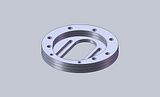
These topmounts are currently fabricated from 3 x 8mm steel plates cut with a 2D CNC laser cutter. These plates are held together using 4 x 8mm and 2 x 6mm studs fusion welded at both ends. If my design yields good results, I will consider fabricating them from a 1 piece lighter grade material (such as aluminium).


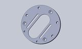
This is the design which later went for cutting


Final product installed


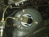
I was so eager to test fit, that i forgot to take pics of the topmount before installing it :doh:


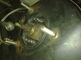
I have left the O/S untouched with the original Tein Topmount and alignment. When I have time I will disconnect the tie rod from the N/S and align both wheels with 0 toe, and make a comparison between sides.
 

campbellju

Moderators
Staff member
Looks like a nice piece of work trip.

Can you rotate the top plate so it only gives additional castor? Before my engine failed recently I was playing with King pin inclination to give back the steering feel people felt was lost with the castor mod. Castor does give a more "wooden" feel but I found the heaviness was as much down to the additional KPI as the castor.

I played with minimum and maximum KPI by adjusting the camber plate at the top but then compensating at the bottom to give the camber I wanted.

Too little KPI made the steering light again but too light for my liking. In the middle (standard) is close enough.
 

stumo

Active Member
What Jim is trying to say is....

Trip, if you're going to make your own strut tops, you're better off not having any camber adjustment (side to side movement) and having the top of the strut placed at the back of the hole (in the strut tower).

ie you just move the original position rearward.

The original camber mod was done in such a way (turning the strut top) because you only had to drill one hole and then turn the strut top.
 

Trip

New Member
Thanks for your comments.

The topmounts i did cannot be mounted for 0 camber but it would be a very easy fix (on paper) to turn round the mounting holes and send them for laser cutting.

When camber bolts or the camber mod is used to add negative camber, you are effectively decreasing the KPI angle (and altering the scrub radius) . which (if i understood you well) you are compensating by adding more Caster at the top.

Would you be able to have enough negative camber by just altering the mounting point at the shock ? I only managed to get 2.5deg (decimal) of negative camber and 2deg of caster using both the caster and camber mod. With these new topmounts, i am hoping to get more caster and same camber or a little bit more negative camber (to help with the tight chicanes). Please bare in mind that my car is fully stripped and most metal panels replaced with GRP.

The steel i am using and CNC cutting isn't that much expensive, so it would be great experimenting with different combinations before going for the expensive material :)
 
I

iomegalinux

Guest
pretty cool. for people in america if Trip want to send me the 3D file, i can do the cnc at my job, if i have many order, it would cost only the material.
by the same way same on shipping.

i just past the whole thread you linked and there's a way too much information for a non-sticky thread ;)
 
Last edited by a moderator:

campbellju

Moderators
Staff member
changing camber at the top mount has the biggest effect on KPI and scrub. The camber mod at the bottom has minimal effect on KPI and scrub.

You can keep drilling out your lower strut mount to give whatever camber you want.

Stu and I did this on mine when we tried minimise the KPI. We saw >-3.5degs at one point without even trying. We were targeting -1.5degs :doh: (I wanted more again afterwards)

....Stu will be along shortly to better explain my overcomplicated explanation ;-)
 

Trip

New Member
I beg to differ on this one. KPI is the angle between the vertical axis of the wheel and the virtual mounting points of the shock to the hub.


this will explain it better


When you adjust camber from topmounts you are incling the coilover, hub and wheel as a whole piece and KPI is not changed. But if you adjust camber only using camber bolts, you are only incling the hub and wheel, and not the coilover.
 

stumo

Active Member
And I beg to differ too.

KPI is the angle between the vertical and the line drawn between the bottom ball joint and the top mounting (nothing to do with how the hub is attached to the strut).

As you adjust the top mounting in and out, the KPI increases and decreases (and it changes scrub too).

KPI will not change when you adjust camber at the bottom of the strut and has minimal effect on scrub.
 
Last edited:

Trip

New Member
I think we are talking about two different things here. The king pin axis will change just as you are describing by moving either the top mounts plates or the lower ball joint, but it will not change the KPI angle.

King pin inclination is the angle between the King pin axis and the wheel vertical axis (wheel centre line) and that cannot be changed from the top mount plates since the strut is fixed to the hub. This angle is determined from the hub design and its mounting points.

I have found this diagram and deleted not needed labels and added in red the KPI angle. As you can see changing the king pin axis will not alter the angle of KPI since the wheel centre line will also move with the king pin axis


campbellju

Moderators
Staff member
I'm with Stu on this one trip. Your ball joint is fixed so if you look a the diagram above, moving the strut at the camber plate will directly affect the kpi.

Adjusting the camber at the bottom changes the inclination of the hub/wheel but still can't move the ball joint so your KPI stays the same.

You've said the same as this below but you've forgotten the bottom ball joint isn't going anywhere.

When you adjust camber from topmounts you are incling the coilover..................

But if you adjust camber only using camber bolts, you are only incling the hub and wheel, and not the coilover.
 

Trip

New Member
Exectly my point Jim,

As i originally said and I quote

When you adjust camber from topmounts you are incling the coilover..................
I hope we do agree on this statment :)

But when you do so you are also incling the wheel hense why they are called camber adjustment plates. Since both strut hub and wheel incline together (since they are bolted together) the KPI angle does not change.


Adjusting the camber at the bottom changes the inclination of the hub/wheel but still can't move the ball joint so your KPI stays the same
Adjusting the camber at the bottom will only incline the hub and wheel. The coilover remains where it is. So you are reducing (for negative camber) the angle (KPI) between the king pin axis and the wheel centre line.
 

Trip

New Member
check out these hubs designs, these are for double wish bone setup but the principle remains the same. The KPI angle are set in the design of the hub nothing more.


stumo

Active Member
Trip, the KPI is set in those hubs because the mounting points are fixed. Although i would argue that once you add camber you will be adding KPI.

as i said earlier, KPI is the angle between the vertical and the line drawn between the bottom balljoint and the top mounting.

you can see it in your own picture....

The wheel center line is vertical, and always is, even when you add camber to it.

 
Last edited:

campbellju

Moderators
Staff member
check out these hubs designs, these are for double wish bone setup but the principle remains the same.
The principle doesn't which is possibly where your confusion is coming from.

On a double wishbone the two pivot points are the top and bottom of the hub. On a Macpherson setup it's the bottom ball joint and the Strut top as the top of the hub where it meets the damper doesn't pivot.
 

Trip

New Member
Ok guys..

I have drew a front view of a mcpherson strut assembly to show the different angles. Nothing is to scale but this will give you an idea of my views regarding KPI :)


First pic. Basically the wheel is at 0 Deg camber with no camber compensation at the top plate nor at the hub. The KPI angle is 13.57 Deg. As you can see the king pin axis is drew from the lower balljoint up to the coilover top plates and the wheel centre line is parallel to the disk brake.
 

Trip

New Member
Second Pic,

I have added lots of negative camber simulating camber change by adjusting camber from the coilover's top plates. As you can see the KPI angle remains the same (13.57 Deg) since the wheel vertical axis moves with the whole assembly.


Trip

New Member
Third pic,

I left the coilover untouched as the first pic, but adjusted camber using ONLY the camber mod by offsetting the mounting of the coilover with the hub. As you can see the KPI angle has decreased to 6.35 Deg while still retaining the same coilover position and king pin axis as the first pic.


campbellju

Moderators
Staff member
You are clearly an artist trip, lovely drawings.

You've got the correct concept for the line from strut top to the ball joint.

The wheel centre line in the first pic and the true centre line in this one are the same thing and they are always vertical. If you do that then your first pic and third pic are similar whilst your second pic is different.

 
Top