rocketdog
New Member
Ok so I bought one of these and of cause as many of you have found out all the instructions are in Japanese which makes a very simple installation very hard. I actually could not find anything particularly informative in English regarding installation in a GTIR anywhere on the internet. This may just be my lack of ability to find things but has resulted in me putting this little box on the bench with a power supply, signal generator, and oscilloscope to find out exactly what each wire does which I think is far more useful than a book of instructions in Japanese. Ive also put together a way to install it which does not involve cutting a single wire and works beautifully, so I thought I would share it!
So here goes:
Red: 12v+ this obviously needs to be a switched (ignition) live.
Black: 0v
White: Speed signal from gearbox sensor (normally but in the pulsar Ive used the half frequency signal modified by the speedo) . (This input will trigger from a range of waveforms right down to about 1v if you need it to)
Yellow: This outputs a square wave of the same frequency as the white in but stops increasing the frequency at the equivalent of 176Km/h. This wire is what end up feeding the ecu at pin 32 (yellow and green wire)
Blue: This also outputs a square wave which tracks the white input frequency but it carries on increasing after 176 km/h. This can be used to drive a speedo but not in the pulsar. Why? Because pulsar speedo also acts to half the frequency of the ongoing signal to the ecu. The gearbox signal wires in the pulsar (that is the green and red wires that run to the center block connector on the back of the clocks) run at twice ecu speed signal frequency and is reduced by the circuit in the back of the speedo. So the SLD has to be placed in circuit after the speedo.
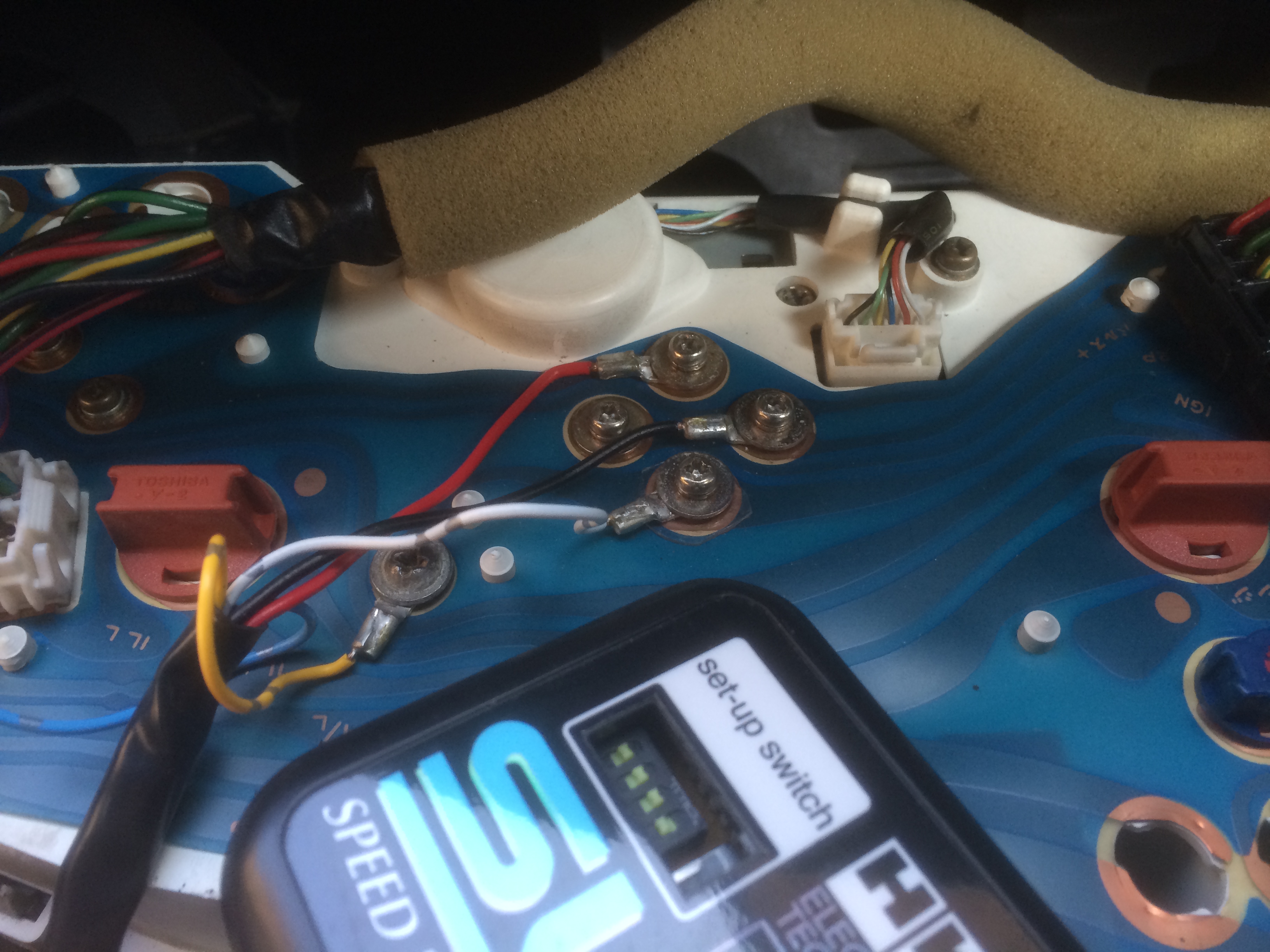
It just so happens that everything you need to wire in the SLD is available on the screw terminals at the back of the speedo without even cutting a wire, ill include a picture to show how. Solder ring connectors on the ends of the SLD wires (all except the blue!, just tape that out the way!) Screw the red and black under the terminals shown for the power, now the white one is the only tricky one because it needs to pick up the signal coming from the screw but not let the scew contact the track underneath in the normal manner. Youll need to use or make a little plastic washer to place under the screw and ring connector so there insulated from the track, and now finally introduce the new false signal into the track and for this nissan have kindly left an unused track connector so just use a self-tapping screw to secure the yellow wire in the place shown.
The Switches: The bigger of the five DIP switches changes the output signal to the ecu from a 12v square wave when down to a 6v square wave when up. Use the 6v up position for the GTIR. The other switches do absolutely nothing I could find. At a guess they are for fine tuning the way the SLD triggers on the incoming signal but that’s just a guess because it seems very good at triggering on just about anything, I did every test I could think of and it behaved identically in all switch positions. Id be interested if anybody has found anything different.
www.heatwizard.co.uk/pulsarclockshks.jpg

So here goes:
Red: 12v+ this obviously needs to be a switched (ignition) live.
Black: 0v
White: Speed signal from gearbox sensor (normally but in the pulsar Ive used the half frequency signal modified by the speedo) . (This input will trigger from a range of waveforms right down to about 1v if you need it to)
Yellow: This outputs a square wave of the same frequency as the white in but stops increasing the frequency at the equivalent of 176Km/h. This wire is what end up feeding the ecu at pin 32 (yellow and green wire)
Blue: This also outputs a square wave which tracks the white input frequency but it carries on increasing after 176 km/h. This can be used to drive a speedo but not in the pulsar. Why? Because pulsar speedo also acts to half the frequency of the ongoing signal to the ecu. The gearbox signal wires in the pulsar (that is the green and red wires that run to the center block connector on the back of the clocks) run at twice ecu speed signal frequency and is reduced by the circuit in the back of the speedo. So the SLD has to be placed in circuit after the speedo.
It just so happens that everything you need to wire in the SLD is available on the screw terminals at the back of the speedo without even cutting a wire, ill include a picture to show how. Solder ring connectors on the ends of the SLD wires (all except the blue!, just tape that out the way!) Screw the red and black under the terminals shown for the power, now the white one is the only tricky one because it needs to pick up the signal coming from the screw but not let the scew contact the track underneath in the normal manner. Youll need to use or make a little plastic washer to place under the screw and ring connector so there insulated from the track, and now finally introduce the new false signal into the track and for this nissan have kindly left an unused track connector so just use a self-tapping screw to secure the yellow wire in the place shown.
The Switches: The bigger of the five DIP switches changes the output signal to the ecu from a 12v square wave when down to a 6v square wave when up. Use the 6v up position for the GTIR. The other switches do absolutely nothing I could find. At a guess they are for fine tuning the way the SLD triggers on the incoming signal but that’s just a guess because it seems very good at triggering on just about anything, I did every test I could think of and it behaved identically in all switch positions. Id be interested if anybody has found anything different.
www.heatwizard.co.uk/pulsarclockshks.jpg
Attachments
-
 127.8 KB Views: 2
Last edited: